Wiring diagram peweta, All prices are subject to change without notice packing and shipping cost (see page 203) as well as vat for deliveries within germany added. 183.
Hot tub wiring diagram askthe asktheelectrician, This information serves as a typical spa or hot tub wiring diagram to help inform you about the process and electrical wiring components. this article contains.
Owner’ guide th115afga / th115afgb, Th115afga / th115afgb 5 english display temperature operation mode icon (see pages 16 & 17) period (see page 14) time number of flames varies according to.
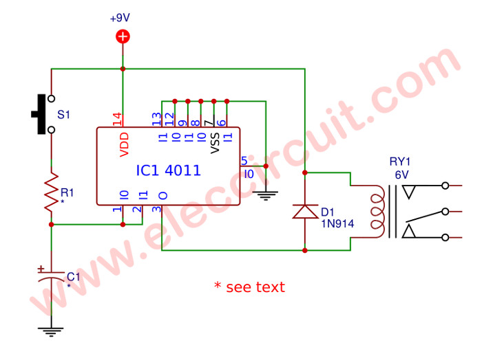
 Time delay for relay using cd4011 – electronic projects circuits | Source: www.eleccircuit.com
 Timer not working.mp4 youtube | Source: www.youtube.com
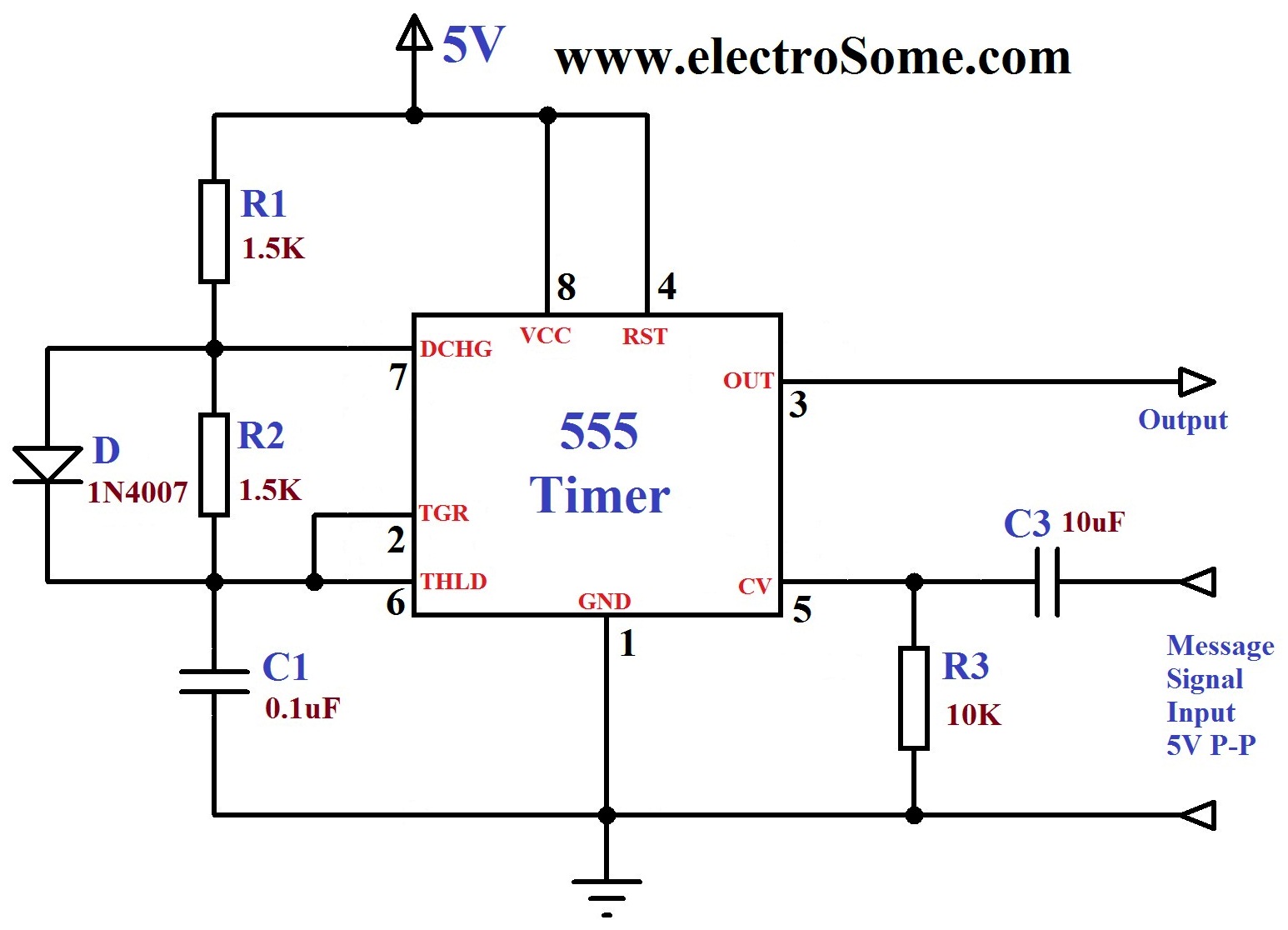
 Fm generation using 555 timer | Source: electrosome.com
 Neo6m gps module | Source:hobbyking.com
I² wikipedia, I²c uses only two bidirectional opendrain lines serial data line (sda) and serial clock line (scl) pulled up with resistors. typical voltages used are +5 v or +3.
Flipflop (electronics) wikipedia, In electronics a flipflop or latch is a circuit that has two stable states and can be used to store state information. a flipflop is a bistable multivibrator..
Comments
Post a Comment